Warning: Undefined array key 0 in /www/wwwroot/acrel.pl/wp-content/plugins/sytech-fronteditor/sytech-fronteditor.php on line 342
Warning: Attempt to read property "dup_id" on null in /www/wwwroot/acrel.pl/wp-content/plugins/sytech-fronteditor/sytech-fronteditor.php on line 342
General
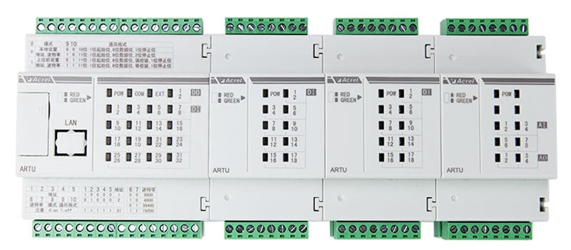
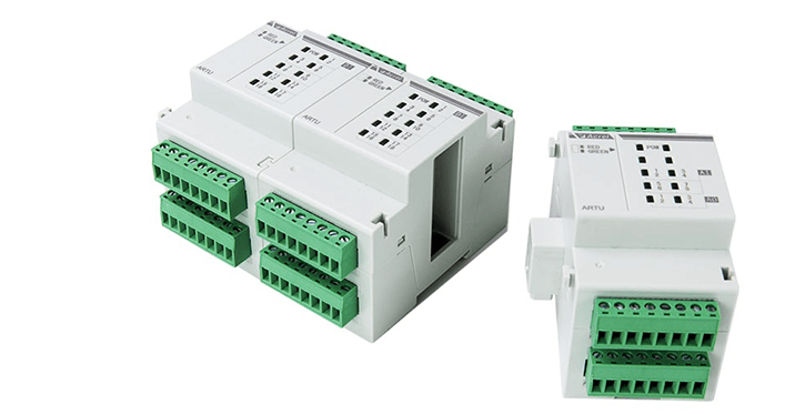
ARTU100 series remote communication& control unit is designed particularly for acquisition of switching value and remote relay output in applications like intelligent distribution and industrial automation. It implements the data exchange through communication and upper computer monitoring system.
Features
1) 2-way 10-100mbits adaptive Ethernet communication, support IPV4, IPV6.
2) Support Web page parameter configuration, UDP broadcast, SNMMP network management, DHCP automatic access IP.
3) It can realize 8-way Sever/Client function, and realize 8-way client connection or 8-way server connection at the same time.
4) 8-way RS485 communication, baud rate support 1200-115200 can be set, data bit, check bit, stop bit can be set;each 485 can be connected to 30 meters.
5) The protocol conversion between MODBUS TCP and MODBUS RTU can be realized.
Specification
Power Supply
AC/DC 85-265V 、 DC48V
Powe Consumption
≤9W (excluding modules); ≤15W (including modules, up to 3 modules)
Model
ARTU100-K32
32-path DI (active/passive, optional)
ARTU100-K16
16-path DI (active/passive, optional)
ARTU100-KJ8
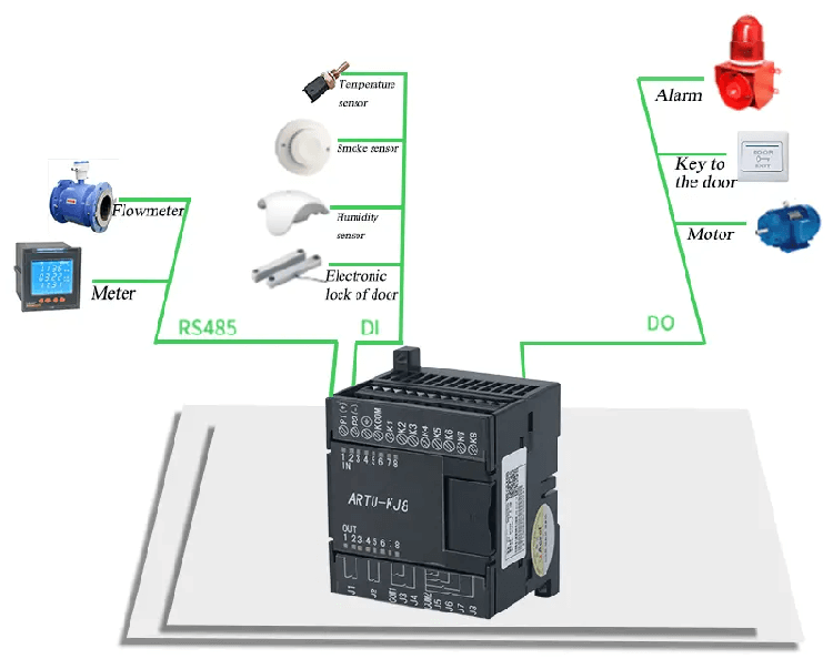
8-path DI (active/passive, optional); 8-path DO, output mode: relay normally-open contact output,contact capacity; AC 250V/3A DC 30V/3A;
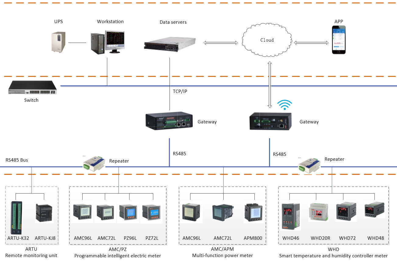
Realizes the data conversion from Modbus protocol to TCP/IP protocol and communicates with the equipment.
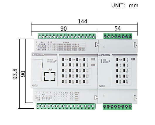
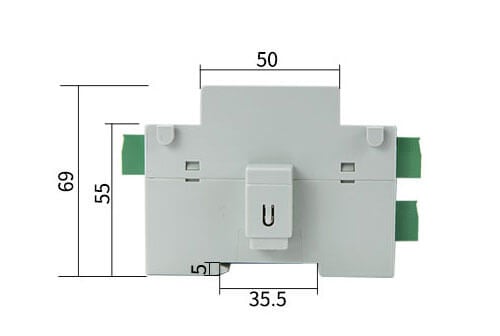
Dimension
Specification
Indicator Light Description
1. POW refers to the power light.2. COM refers to the communication light.3. EXT refers to the module communication light.4. The number refers to the channel number (for example, K16 refers to DI1-DI16), the odd number refers to the red light, and the even number refers to the green light. (See the table below for specific information of indicator lights.)